Related Questions on Engineering Drawing. Set the divider to a convenient length and mark off seven spaces on AC.
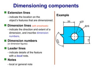
Engineering Drawing Chapter 07 Dimensioning
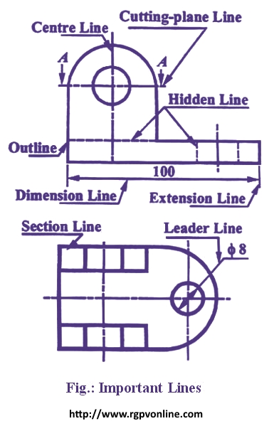
These lines are drawn to make the section evident.
. In technical drawings the standards of the leaders and arrows are very important. A leader line consists of two parts. B One end of the leader terminates either in an arrowhead or a dot.
For general engineering drawings the types of lines recommended by the Bureau of Indian Standards shown in table 2 must be used. Leader line Dash thick line Hidden. Leader line in engineering drawing Nail artwork conjures up Every person.
The thickness of the lines must be chosen according to the type and size of the drawing from any of the six groups given in Table 1. Up to 24 cash back Continuous thin Dimension lines leader lines extension lines Construction lines 2H Hatching lines. The wrong statement about leader line is _____________.
Should you be a colorful Lady Then you can certainly take up brighter color tones for the nails if you want delicate factors so certainly your temper will get on nail paints that happen to be a bit boring and less flashy. Continuous thin wavy Irregular boundary lines short 2H. This line is used to represent the center line for circles and arcs.
A Continuous thick line. Continuous thin line find its application in engineering drawing as Dimension line Projection line Leader line. You can see the general standards that are used generally below.
This is used to hide it without using hide method it is not shown at all until show method is called. C Continuous thin wavy line. Consider thin lines are 03 mm and thick lines 06 mm in technical drawing.
This line is located in front of cutting planes outlines of adjacent parts censorial Lines and to state center of gravity. Swing the pencil back and forth between the points barely touching the paper until the direction is clearly established. Engineering Working Drawings Basics Page 1 of 22 Engineering Working Drawings Basics Engineering graphics is an effective way of communicating technical ideas and it is an essential tool in engineering design where most of the design process is.
Where a leader line is used to point towards the feature being dimensioned. Looking at the drawing. Leader or Pointer Lines.
Dashed Thin Lines with Dots. Leader lines and Termination of the dimension line. Technical Drawing Line Types.
Leader Line In Engineering Drawing. End of the extension line. Leader line is drawn may be 30 or 60 to the bottom of dimensions.
For More Engineering Drawing MCQ Click Here. Leader Line Leaders are more thin lines used to point to an area of a drawing requiring a note for explanation. You can create leader lines with blocks and notes in 2D panel layouts and harness drawings.
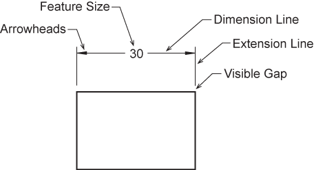
These are drawn may be vertical or inclined to indicate the height of the dimension figure. Introduction to lines. A leader line is a line referring to some form of feature that could be a dimension an object or an outline.
Sometimes leaders are used in place of extension and dimension lines especially when dimensioning arcs and circles. Dashed Thin Lines with Double Dots. The article talks about Line Types and Dimensions in Engineering drawing.
A drawing leader consists of an arrow and a text. The leader line is never shown until the button is clicked. This gives rise to number of important line types.
B Long chain thin line. Vi Leader Lines A leader or a pointer is a thin continuous line connecting a note or a dimension figure with the feature to which it applies. They are uniformly spaced about 1 mm to 2 mm apart.
Leader linea thin solid line used to indicate the feature with which a dimension note or symbol is associated- Leader lines are generally a straight line drawn at an angle that is neither horizontal nor vertical Leader lines are. They are used for center lines. Dimension Marking with Center Lines in Engineering Drawings.
To create a leader line on the Draw tab under Annotation click. Also Can i add Positional Tolerance without any datum like mentioned in the diagram. Below are the uses of Dashed Thin Lines with Dots.
C The leader is drawn vertical or horizontal or curved. Avoid dimensioning to hidden lines wherever possible. Leader line is drawn may be 30 or 60 to the bottom of dimensions.
A A leader line is a thin continuous line connecting a note or a dimension figure. Draw the line firmly with a free and easy wrist-and-arm motion. The expression of details in terms of numerical.
This line is used to represent the location of a cutting plane. A leader line is a line referring to some form of feature that could be a dimension an object or an outline. Hi I am new to Engg Drawing and confused if I can Mark Dimension with Center Lines in Engineering Drawings like the attached file.
A leader line is a thin line on a design or blueprint that is used to connect a dimension line with a particular area or point on the drawing. They serve as axis lines of symmetrical drawings. Leaders should have a uniform and consistent appearance at all drawings independently of the drawing scale.
D Use of common leaders for more than one feature should never be made. This line is similar to the Dash Thin Lines with Dots except that it has double dots within it. For general engineering drawings the types of lines recommended by the Bureau of Indian Standards shown in table 2 must be used.
They are used as line of symmetry. They are generally used as thin lines. Continuous thin line find its application in engineering drawing as Dimension line Projection line Leader line.
A leader may also be used to indicate a note or comment about a specific area. Just as the points can be arranged in a number of fashions. A type B line thin continuous straight going from the instruction to the feature.
13The primary unit of measurement for engineering drawings and design in the mechanical industries is the. B Long chain thin line. Hold the pencil naturally.
For general engineering drawings the types of lines recommended by the Bureau of Indian Standards shown in table 2 must be used. The most fundamental parameter to define any engineering design is a point. Uniform leaders can be easily achieved in modern CAD software using annotative.
7 Thin chain line find its application as. The set of these points is called a line. These are thin continuous lines drawn from a dimension figure to the feature to which it refers.
A 14To draw the leader line which type of the following line is used. Dimension Marking with Center Lines in Engineering Drawings. All of the above.
Spot the beginning and end points. This line is used to show hidden edges of the main object. Leader Hatching type lines must be drawn thin and continuous.
More specifically the arrow size arrow inclination the text size allow line weight etc should all be the same for all leaders in a drawing. Var line new LeaderLinestartElement endElement hide. This can be a dot if the line ends within the outline of the part an arrow if the line touches the outline or centre line.
One end of the leader terminates either in an arrowhead or a dot. An Engineering drawing should contain the details regarding the sizes besides giving the shape of an object. 7 Thin chain line find its application as.

Dimension Guidelines Introduction To Engineering Design Ppt Download
Leader Lines Toolnotes

Engineering Drawing Dimensioning Part 1 Youtube

Extension Lines Drafting Joshua Nava Arts
Draw The Following Lines Used In Projection I Extension Line Ii Leader Line Iii Construction Line न म नल ख त ल इन क ख च Solutions Ed Question Answer Collection
What Are The Types Of Lines In Engineering Drawing Quora
Dimension Appearance And Technique

What Are Lines Types Of Lines In Engineering Drawing Youtube
0 comments
Post a Comment